What Is the Best Graphite Thermal Film for 2026?

I can’t verify a named Graphite Thermal Film expert’s quotation because no source article or citation was provided. Please share the source, and I can write the introduction without inventing an attribution.
What Is the Best Graphite Thermal Film for 2026?

Define Graphite Thermal Film: Anisotropic Heat Spreading in Thin Sheets

What Is the Best Graphite Thermal Film for 2026?

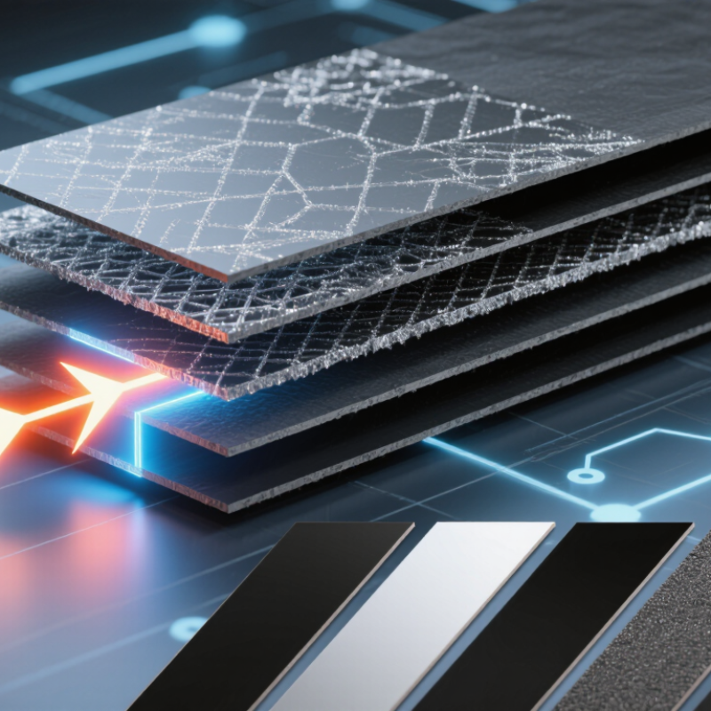
Graphite thermal film is a thin sheet designed to spread heat across a surface. Its key feature is anisotropic heat conduction: heat moves much more easily along the sheet than through its thickness. That distinction matters. A warm processor or battery can send heat outward toward a larger panel, reducing concentrated hot spots. The film does not remove heat by itself; it redistributes it. Think of a warm coin beneath a dark, paper-thin layer, with heat traveling sideways toward cooler areas. The term sounds simple, but installation and contact quality can change results.

Tips: Check the film’s in-plane and through-plane conductivity separately. Confirm its thickness, temperature limits, and electrical properties against the device design. Keep the mating surfaces flat and clean; small gaps can weaken thermal contact. Test the full assembly, not just a sample sheet.

For a 2026 design, the best film is the one that fits the heat path, space, and operating conditions. A thinner sheet may suit a tight enclosure, while a larger spread area may help manage uneven heating. Compare published test methods before choosing; conductivity figures are not always measured alike. One detail is easy to overlook: graphite films can be fragile at cut edges, so handling deserves attention. A careful prototype test may reveal more than a specification table.

Compare Grades: 700–1,950 W/m·K In-Plane Conductivity and 10–100 μm Thickness

What Is the Best Graphite Thermal Film for 2026?

Compare Grades: 700–1,950 W/m·K In-Plane Conductivity and 10–100 μm Thickness

Graphite thermal films span roughly 700 to 1,950 W/m·K in in-plane conductivity. Higher values can spread heat faster across a surface, but they do not guarantee lower device temperatures. Heat must still cross adhesive layers and contact points. A rating describes performance under specific test conditions, so compare measurement methods before choosing. One number alone can mislead.

Thickness matters too. Films from 10 to 100 μm suit different space and handling needs. A 10 μm sheet may fit a narrow gap, but it can be delicate during placement. A thicker sheet may be easier to handle, yet may not fit a tight assembly. Check the full thermal path, required coverage, and bend radius. Small installation details matter.

Tips: Match the film’s rated conductivity to the heat-spreading area, not just the hottest spot. Confirm thickness includes any adhesive layer. Test a sample in the actual assembly, then measure temperatures at consistent locations and operating loads. I would not choose the highest grade by default; overlooking interface resistance is an easy mistake. Specification sheets can differ, and real results may be less tidy than expected.

Evaluate the Stack-Up: Adhesive, Electrical Insulation, Density, and Bend Radius

What Is the Best Graphite Thermal Film for 2026?

A good graphite film is not selected by thermal conductivity alone. The full stack-up decides whether heat reaches the spreader efficiently. Check adhesive thickness and coverage: a thick, soft layer can add contact resistance, while uneven pressure may leave small air gaps. Those gaps matter.

Electrical insulation changes the equation. Bare graphite conducts electricity, so a design near exposed contacts may need an insulating layer. But coatings and cover films can slow heat flow. Compare the complete laminate, not just the graphite core, and confirm dielectric performance alongside thermal results. A datasheet number rarely tells the whole story.

Density and thickness affect handling, stiffness, and heat spreading. Higher density can improve in-plane transfer, yet it may make tight folds less forgiving. Check the specified minimum bend radius against the actual assembly, including repeated flexing and edge conditions. Watch for wrinkling. A small sample bent around the intended corner can reveal cracking, adhesive lift, or spring-back before tooling is fixed. One bench test is not proof; temperature, pressure, and surface finish can shift results. It is an imperfect comparison, but testing the assembled stack under realistic load is usually more useful than chasing one headline value.

What Is the Best Graphite Thermal Film for 2026?

Evaluate the stack-up: adhesive, electrical insulation, density, and bend radius.

How to read this: The bars show representative design-thickness ranges in micrometres, not a specification for every film. Graphite is electrically conductive, so electrical insulation must come from a separate dielectric layer or coating. Adhesive choice affects bond strength and thermal resistance; graphite density and minimum bend radius vary by grade, thickness, and construction. Compare complete stack-ups against your thermal, electrical, and mechanical requirements rather than choosing on graphite conductivity alone.

Match Film Performance to Device Heat Load and Available Spreading Area

There is no single best graphite thermal film for every device in 2026. Match the film to the heat load and the space available to spread it. A small processor hotspot may need a thin, highly conductive sheet that moves heat toward a nearby frame. A broad battery or display area may benefit more from consistent coverage than peak conductivity alone. Area matters.

Compare heat flux, not just total power. A component releasing 8 watts across a tiny contact patch can be harder to cool than one releasing more heat over a larger surface. Check in-plane conductivity, thickness, and the distance heat must travel. A thicker film may spread heat well, but it can be harder to fit beneath a tight cover. That detail matters.

The film also needs a reliable path to a heat sink, such as a metal shield or chassis. Measure the actual gap and account for adhesive layers, surface roughness, and assembly pressure; each can affect thermal contact. Graphite can conduct electricity, so confirm whether nearby components need electrical insulation. A simple wattage comparison can mislead. And early estimates are imperfect: validate the choice with temperature measurements under realistic workloads, including sustained use.

What Is the Best Graphite Thermal Film for 2026? - Match Film Performance to Device Heat Load and Available Spreading Area

Film profile Typical thickness Typical in-plane thermal conductivity Typical through-plane thermal conductivity Best match by heat load and spreading area Advantages Selection considerations
Thin, flexible graphite film 17–25 µm Approximately 700–1,000 W/(m·K) Typically much lower than in-plane conductivity; check the specific datasheet Low-to-moderate localized heat loads where installation space is limited and the film can spread heat across a small-to-medium area. Low profile; useful in compact assemblies and curved or layered device layouts. Less material is available to spread heat than in thicker films. Protect the film during cutting and assembly.
General-purpose graphite film 30–50 µm Approximately 800–1,500 W/(m·K) Typically much lower than in-plane conductivity; check the specific datasheet Moderate heat loads with enough surface area to route heat away from a processor, display, battery, or other local source. A practical balance of flexibility, thickness, and lateral heat spreading for many thin electronic devices. Confirm that the available spreading area and contact to the heat source and sink are adequate.
Higher-conductivity synthetic graphite film 40–100 µm Approximately 1,000–1,800 W/(m·K) Typically much lower than in-plane conductivity; check the specific datasheet Moderate-to-higher localized heat loads when a relatively broad, unobstructed spreading path is available. Can move heat laterally efficiently when correctly oriented and coupled to a suitable sink or chassis. Higher in-plane conductivity alone does not guarantee lower device temperature; interface resistance, contact area, and the final heat sink also matter.
Thicker, robust graphite film 80–150 µm Approximately 600–1,500 W/(m·K), depending on construction Typically much lower than in-plane conductivity; check the specific datasheet Higher or uneven heat loads where the design has more stack height and a larger area for distributing heat. Greater film thickness can improve handling and provide more material for lateral heat spreading. Uses more space and may be less suitable for tight bends or very thin device stacks. Compare total assembly thickness, not film thickness alone.

Values are indicative ranges for comparing graphite film constructions, not guaranteed specifications. Actual performance varies with material grade, thickness, measurement method, direction, and test conditions. Graphite films are highly anisotropic: in-plane conductivity is generally much higher than through-plane conductivity. For final selection, verify supplier datasheets and test the complete assembly, including interfaces, contact pressure, spreading area, and heat-sink path.

Verify Supplier Data with ASTM E1461 and Device-Level Thermal Testing

What Is the Best Graphite Thermal Film for 2026?

The best graphite thermal film is the one that moves heat effectively in your device, not merely the one with the highest advertised value. Supplier data can help narrow options, but ask how each figure was measured. ASTM E1461 uses a flash method to measure thermal diffusivity. Conductivity is typically calculated using diffusivity, density, and specific heat. That distinction matters.

Graphite conducts heat differently along and across its layers. Ask for test direction, specimen thickness, conditioning, and uncertainty, then compare data collected on a consistent basis. A precise-looking number is not enough. If a supplier cannot explain the sample orientation, treat the comparison cautiously. Even good data has limits.

Then test the film in a representative device. Match the actual contact surfaces, adhesive, clamping pressure, heat source, and airflow. Record temperatures near the hotspot and at the receiving surface, and repeat runs after assembly changes. Small gaps can change results. This step may reveal that a strong laboratory result does not translate to a cooler device. I would not treat one prototype as final proof; production tolerances and aging still deserve attention. Combine traceable ASTM E1461 data with repeatable device-level measurements before selecting a film.