How to Choose Graphite Cooling Film in 2026?
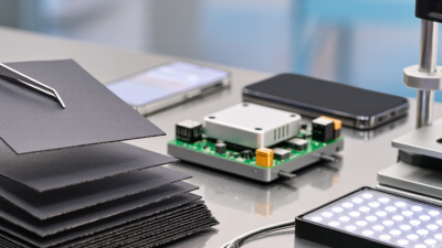
Choosing Graphite Cooling Film in 2026 requires more than comparing thermal conductivity figures. Modern smartphones, tablets, wearables, and compact industrial devices generate heat in increasingly crowded spaces. The film must move heat away from sensitive components while fitting strict thickness and weight limits. A product that performs well in a laboratory may behave differently inside a sealed device. Real conditions matter.
This guide examines the practical factors behind a reliable selection. These include thermal conductivity, in-plane heat spreading, thickness, flexibility, surface treatment, electrical insulation, and adhesive compatibility. Manufacturing consistency also deserves attention. Small variations can affect contact with chips, batteries, or metal frames. Technical datasheets provide useful evidence, but independent testing remains valuable. Ask for test methods, temperature ranges, and sample results.
There is no universal best film. That is the uncomfortable part. A high-conductivity grade may fail when bending, compression, or installation space becomes critical. A cheaper option may appear sufficient, yet create uneven hot spots over time. Engineers should compare measured performance inside the target device, not only rely on supplier claims. In 2026, responsible buyers should also review traceability, quality controls, environmental data, and supplier support. Careful selection takes time. It can prevent expensive redesigns later.
What Is Graphite Cooling Film and How Does It Work?
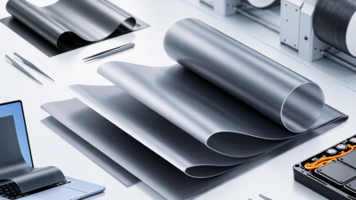
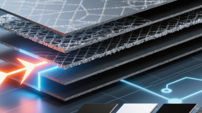
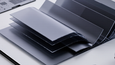
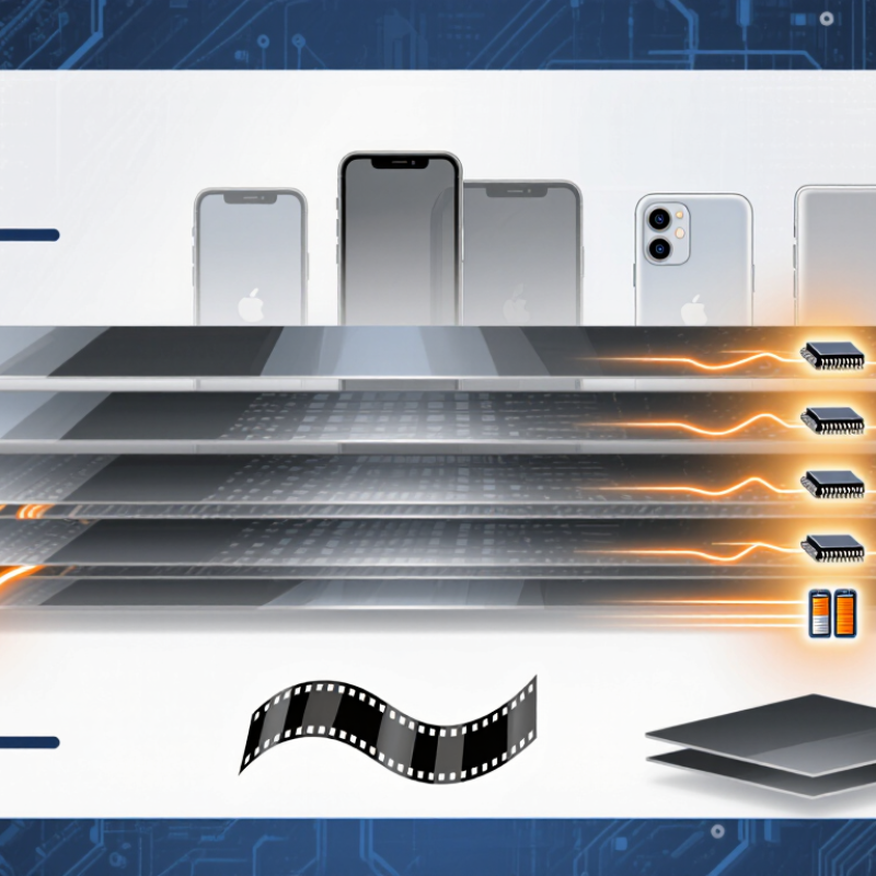
Graphite cooling film is a thin heat-spreading layer made from highly oriented graphite. It is not a paste. Its main job is lateral heat movement, not direct heat removal. Heat from a processor enters the film through its thickness, then spreads across the plane toward a larger surface area. This reduces concentrated hot spots beneath cameras, batteries, and display modules.
In-plane thermal conductivity can exceed 1,000 W/m·K in high-grade synthetic graphite sheets, while through-plane conductivity remains far lower. This difference is critical. A 2024 Grand View Research report estimated the global thermal interface materials market at about USD 3.6 billion in 2023, with strong growth expected through 2030. MarketsandMarkets also identifies thinner electronics and higher power density as major thermal-management drivers. These figures support demand, but they do not prove that every graphite film will cool every device.
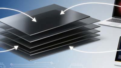
When choosing film in 2026, check in-plane conductivity, thickness, density, compressibility, and electrical insulation requirements. Measure performance near the actual heat source, not only on a supplier’s laboratory sheet. A 25-micrometer film may fit a narrow phone frame, but wrinkles can create air gaps around a curved battery. That weakens heat spreading. In testing, I would compare infrared images before and after installation, then repeat measurements under sustained load. The advertised conductivity may look impressive. Real assembly conditions are less perfect. A thermal engineer should also inspect adhesive aging, folding damage, and contact pressure before final approval.
How to Choose Graphite Cooling Film in 2026? - What Is Graphite Cooling Film and How Does It Work?
Graphite cooling film is a thin, flexible thermal-spreading material that transfers heat rapidly across its plane and distributes localized heat over a larger surface area. The values below are typical engineering ranges; actual performance depends on graphite grade, thickness, orientation, adhesive construction, surface treatment, and test method.
| Selection Dimension | What It Means | Typical Data or Range | How to Choose |
|---|---|---|---|
| Material Type | Describes the graphite structure used to spread heat. | Synthetic graphite, pyrolytic graphite, expanded graphite, or graphite composite film. | Use synthetic or pyrolytic graphite for thin electronic devices requiring high in-plane thermal spreading. Consider composite construction when electrical insulation or mechanical reinforcement is required. |
| In-Plane Thermal Conductivity | Indicates how efficiently heat moves along the surface of the film. | Approximately 300–1,500 W/m·K for many commercial graphite sheets; premium highly oriented grades can be higher. | Choose a higher value when the heat source is concentrated or when the available spreading area is limited. |
| Through-Plane Thermal Conductivity | Indicates how readily heat passes through the thickness of the film. | Commonly about 5–20 W/m·K, depending on grade, compression, thickness, and construction. | Do not select graphite film by in-plane conductivity alone. Use a thermal interface material or compliant adhesive when heat must cross from a component into the film. |
| Thickness | Affects thermal spreading, flexibility, compressibility, and available installation space. | Approximately 17–250 μm for thin flexible graphite films; multilayer assemblies can be thicker. | Choose the thinnest film that meets the thermal target and mechanical requirements. Confirm the complete stack-up, including adhesive and protective layers. |
| Thermal Resistance | Represents the temperature rise caused by heat flow through a defined path. | For in-plane spreading, a useful estimate is R = L/(k × t × W), where L is heat-flow length, k is in-plane conductivity, t is thickness, and W is width. | Calculate the complete thermal path, including contact resistance, adhesive layers, air gaps, and the final heat sink or enclosure. |
| Operating Temperature | Defines the temperature range in which the graphite film and its construction remain functional. | Bare graphite can tolerate very high temperatures in inert or vacuum environments; adhesive-backed products are commonly limited to approximately 80–200°C, depending on adhesive type. | Use the temperature rating of the complete assembly, not the graphite layer alone. Check continuous, peak, cycling, and storage temperatures separately. |
| Electrical Conductivity | Graphite is electrically conductive, so it may create an unintended electrical path. | Typical graphite films have low electrical resistance in-plane; electrical properties vary significantly by orientation and grade. | Use an electrically insulating cover, coating, or dielectric interface when the film may contact exposed conductors or circuit traces. |
| Density | Affects mass, handling, and the weight of the thermal-management assembly. | Approximately 1.8–2.2 g/cm³ for many dense graphite sheets. | Graphite film is generally lighter than copper at the same volume, making it useful where low mass is important. |
| Flexibility and Bend Radius | Determines whether the film can follow curved surfaces or survive assembly deformation. | Thin films are flexible, but repeated sharp bending can cause cracking, delamination, or loss of surface contact. | Follow the supplier’s minimum static and dynamic bend-radius limits. Avoid creasing the film during die cutting or installation. |
| Surface Emissivity | Controls how effectively the exposed surface radiates heat. | Bare graphite typically has relatively high infrared emissivity, often around 0.7–0.9; coatings and laminates can change this value. | Consider emissivity when the film is exposed to air and can reject heat by radiation. Do not rely on radiation if the film is enclosed or tightly laminated. |
| Adhesive and Interface | Controls contact quality, installation strength, electrical insulation, and part-level thermal resistance. | Common options include pressure-sensitive adhesive, acrylic adhesive, silicone adhesive, thermal paste, and gap-filling interface materials. | Select based on temperature, surface roughness, rework needs, outgassing limits, adhesion strength, and thermal resistance. |
| Chemical and Environmental Resistance | Determines durability in humidity, oils, solvents, dust, and corrosive environments. | Graphite itself is chemically stable in many conditions, but adhesives, coatings, and laminated layers may have narrower limits. | Test the complete assembly under the intended humidity, temperature cycling, vibration, and chemical exposure conditions. |
| Application Fit | Connects the film’s properties with the thermal and mechanical needs of the device. | Suitable for smartphones, tablets, laptops, LED modules, battery packs, cameras, sensors, and compact electronics when heat must be spread laterally. | Choose graphite film for heat spreading. Use a heat pipe, vapor chamber, metal heat sink, or forced-air system when substantial heat must be transported or rejected. |
| Verification Tests | Confirms whether the selected material works in the real product rather than only under laboratory conditions. | Recommended checks include thermal mapping, temperature-rise testing, power cycling, bend testing, adhesion testing, humidity exposure, and electrical isolation testing. | Evaluate the complete assembled device using the actual heat source, enclosure, contact pressure, airflow, and operating duty cycle. |